Tracking System
IRIDIA is currently developing a Tracking System for the robots experiments taking place in the Robotics Arena. The purpose of the Tracking System is to detect the position of all the robots in the Arena, together with recording and storing the frames of the whole experiments.
Hardware
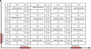
The tracking system is composed by a set of 16 cameras Prosilica GC1600 C, disposed as shown in Figure 1
. The cameras are set in order to have a collective field of view that covers the entire area of the Arena. The cameras are connected to a dedicated computer, the Arena Tracking System Server, through Ethernet connection. The Arena Tracking System Server hosts the API that the users of the Tracking System can exploit to configure, run and record their experiments. (Ref: Alessandro Stranieri, Arena Tracking System)
Software
The Arena Tracking System's API are built on top of the Halcon library. Halcon is a library by MVTec Software GmbH, used for scientific and industrial computer vision applications. It provides an extensive set of optimized operators and it comes along with a full featured IDE that allows for fast prototyping of computer vision programs, camera calibration and configuration utilities. The library also provides drivers to easily interface with a broad range of cameras. (Ref: Alessandro Stranieri, Arena Tracking System)
Licence
IRIDIA owns a Floating Development Licence. That means that the library can be installed on any computer in the local network, but can be used by at most one of them at any time.
Deployment
The Tracking System is composed by the Halcon libraries, the Tracking System binaries, and the user's home directory configuration. Each of those resources are deployed in the Arena Tracking System Server at several levels.
Halcon libraries
Halcon libraries and documentations are stored at /opt/halcon. These libraries are used for the core functions of the Tracking System.
Tracking System binary files and general configuration
These files are the compiled output of the tracking System sources. They are located in /tracking/lib and used as static libraries. The source files are in /home/ats/source. Configuration files that are administrators' duty, such as calibration files and descriptions of marker models are in the directory /tracking/conf.
User home directory
The directory /home/ats/usr_config is the directory that represents the arena_tracking_system directory in each user's home. This directory contains two links to executable files located in /tracking/lib. One link runs the Tracking System with interactive GUI (arena_viewer), the other runs the Tracking System in a non-interactive textual mode. The user's environment is integrated with the directory data where the results of the experiments are stored and the directory conf that contains all the user concerning resources and experiments.
Administrator's guidelines
The Halcon libraries and the development environment HDevelop can be used either remotely from the Arena Tracking System Server or locally by downloading the libraries on your machine.
Access Halcon from the Arena Tracking System Server
The Halcon library is hosted in the Arena Tracking System Server. In order to use the library is necessary to access the node through Secure Shell. There are two available interfaces for this server:
| IP | Alias | Bandwidth | Command |
|---|---|---|---|
|
164.15.10.153 |
liebig.ulb.ac.be |
1 Gbit |
ssh -X <user>@liebig.ulb.ac.be |
|
169.254.0.200 |
10 Gbit |
ssh -X <user>@169.254.0.200 |
To access the 10 Gbit interface you must be connected to the Camera Network. To connect to the Camera Network you must plug your cable in the switch in which all the cameras are connected.
The 1 Gbit interface can be accessed directly from the internet.
Run Halcon on local machine
WARNING: this guide is meant for Halcon developers running Linux 64 bit. Installation process for other OS can be found at http://www.mvtec.com/halcon/download/release/index-10.html but it has not been tested.
- Dowload halcon.tar.gz from the server liebig.ulb.ac.be in /home/ats/halcon.tar.gz
- Extract the content in /opt on your local machine. From the folder where you downloaded halcon.tar.gz:
   sudo cp halcon.tar.gz /opt
   cd /opt
   tar xf halcon.tar.gz
   rm halcon.tar.gz
- Add execution permission:
sudo chmod -R a+x /opt/halcon
- Set environment variables and add paths to path variables (to be done every reboot).
If you are using Bourne shell:
source /opt/halcon/.profile_halcon
If you are using C shell:
source /opt/halcon/.cshrc_halcon
- Connect your cable to the switch used by all the cameras in order to access the Camera Network (currently only the Ethernet port C4 in the Arena is connected to that switch). Then, assign to your local machine a static IP of type 169.254.x.x (but other than 169.254.100.1) with netmask 255.255.0.0.
WARNING: the Camera Network does not provide internet connection. You need to be connected also to the internet while launching Halcon (e.g. through Hashmal Wifi)
- Open a new terminal and run HDevelop:
hdevelop
How to set up the environment
In order to use the Tracking System for an experiment there are few preliminary steps you should be aware of. These steps allow you to set up a suitable configuration of the cameras and build a marker model able to track the robots, according to the environment you need for the experiment.
Set the light intensity of the Robotics Arena
Before tuning any camera, you should first set the same light intensity you are going to use during the experiment.
Tune the cameras' settings
WARNING: calibration file camera_pose.dat is missing for cameras 5, 6 and 12.
- Run HDevelop (see How to use Halcon) and access Image Acquisition Interface:
Assistants -> Open New Image Acquisition
Be sure that the set of cameras you want to tune is switched on.
- Select Image Acquisition Interface and then Detect. In the drop-down list should automatically appear GigEVision.
- Switch to Connection tab. Select from the drop-down list Device the camera you want to tune. The IDs of the cameras are decoded in Figure 1. Then click Connect.
- HDevelop is now connected to the camera and by clicking on Live you can see real time camera streaming.
- Place a robot with marker under the camera. Zoom in on the marker and tune the camera settings until the marker is on focus and the image is clear. To change the focus you should twist the upper ring on the camera's mount. To change the brightness you can use the parameters in the Parameters tab, especially those related to exposure and gain. The same parameters mus be set in the file resources.xml (see How to run an experiment).
You should try to set up the camera in a way that the markers are clear and on focus either in the centre and in the corners of the visual field of the camera.
Acquire and create a marker model
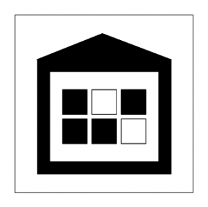
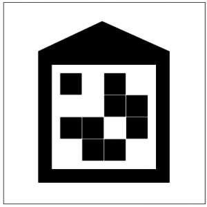
The creation and acquisition of a marker model is a critical step when using the Tracking System. The markers must be placed on top of robots. They are composed by external and internal patterns. The external pattern is the same for all the robots and it is used for detection. The internal pattern must be different for each robot and it is used for the decoding (see Figure 2 and Figure 3).
For a set of printable markers for EPucks and FootBots check File:Printable markers.tar.gz.
The marker for Epucks, for example, has a "house shaped" external pattern in which the roof indicates the orientation of the robot. The internal pattern is a rectangle containing six little black and white squares. Any particular configuration of black and white squares is the encoding of a single Epuck. Six squares allow experiments with up to 64 robots. However, it is safer to avoid configurations which differ from each other for only one square.
In the Tracking System decoding, the Epuck's id is calculated by giving each square a position and a value in a six bits string. In this case, the squares are allocated in the bit string, starting from the less significant bit, from the top left corner to the down right corner. Their value is 1 for white and 0 for black.
Example: in Figure 2 the ID of the robot, following squares from top left to down right, is equal to: 0(black)*2^0 + 1(white)*2^1 + 0*2^2 + 0*2^3 + 0*2^4 + 1*2^5 = 34.
The Tracking System provides a script to acquire and create a marker model. Here is explained how to acquire and create marker models for Epucks.
- In HDevelop, open the file arena_tracking/hdevel/marker_model_creation/acquire_marker_frame.hdev.
This script allows the user to take a picture that will be used to create the marker model.
WARNING: the choice of the marker model is critical for the efficiency and also the correctness of the Tracking System. Your goal is to to create a model that is reliable and efficient. To do so a good habit is to orientate the marker as one of the axes of the camera, in order to have a square on the screen, instead of a rhombus, when it is time to create the model.
- Change the general path variables in the first part of the file, and set CameraID of the camera you chose for this step. Place one or more robots in the scope of the chosen camera and run the script. You now have an image from which infer the marker model.
- Open the file arena_tracking/hdevel/marker_model_creation/inspect_create_marker_model_from_image.hdev and modify the general path variables as done before.
- Run the script, it opens the image just stored by the previous script. Then it stops and prompts you to zoom on the marker you want to extract for the model.
- Run the script again. Now it stops and waits for you draw first the external rectangle of the marker, and then the internal rectangle of the marker. You are also requested to orientate the arrow on the rectangles along with the marker orientation. Right click to confirm your selection.
WARNING: this is also a critical part of the model creation. You should try to be particularly accurate in sizing the two rectangles. The external one must be drawn in the white space within the paper and outside the house shape, taking care not to cut the roof. The same for the internal one, in which you should draw the rectangle in the white padding around the six squares.
- Run the script again. The model has been created and the program shows how many markers it detected in the image. This is a first test of the reliability of your marker model.
To definitely validate the model you can run a few experiments as a test. You can also create several models and pick the best one after the tests.
To actually use your model in the experiment you must add the entry in the file resources.xml and set the right reference in the file experiment.xml (see How to run an experiment).
Create and set up a new Arena Tracking System User
To create a new user for the tracking system the administrator should run the script create_and_setup_new_user.sh available in /home/ats.
./create_and_setup_new_user.sh <new_user_name>
This script creates a new user and builds its environment in order to allow the user to run the Tracking System right away. To set up the environment to an already existing user the script setup_user_home.sh must be run.
./setup_user_home.sh <existing_user_name>
User's guidelines
Every user who is interested in using the Arena Tracking System should ask an administrator to create and/or set up his environment in the Arena Tracking System Server. When the set up is completed the user can access the arena_tracking_system directory in his home directory. The arena_tracking_system directory contains two links to executable files and (arena_viewer and track_no_GUI) and two directories (conf and data). The link arena_viewer runs the Tracking System with an interactive GUI, the link track_no_GUI runs the the Tracking System in a non-interactive textual mode. The conf directory contains editable xml files that must be properly configured by the user before launching any experiment. There are two kinds of xml files: resources and experiment. In order to run an experiment, the user must specify one of each kind of file:
./<link_command> conf/<resource_file> conf/<experiment_file>
For simplicity, the resource file is only one (resources.xml) and it is mostly configured by the administrator. All the other files are experiment files, and must be edited for the most part by the user.
Resource file
In the file resources.xml are stored all the possible resources available for the experiment, along with their parameters and settings.
The grabbers section contains all the possible frame grabbers, i.e. all the cameras and a folder in which images can be stored. Each grabber is described in its grabber section. Here is where the user should set the proper parameters for the cameras to achieve optimal acquisition of the frames. In this section the user can also define his own file grabbers, if he is interested in tracking from a set of frames stored in a particular directory.
The trackers section is where all the available marker models are referenced. For the moment only administrators are allowed to create a new marker model.
Finally, in the cameras section are specified the proper parameter files for each camera. This part should not be edited by the user.
Any of these features can be recalled in the experiment.xml file by their id parameter.
Experiment files
This file must be tailored on the experiment the user is going to run. In the given environment there are some documented examples suitable for each possible usage of the Tracking System. Each of those files is structured as follows:
In the arena_state_tracker section the user can add as many cameras he needs, by editing a new camera_state_tracker entry and providing camera state tracker id, grabber id, tracker id and camera view id. It is best practice to keep the id of each item related to the camera as CST (camera state tracker) or HC (grabber) or C (camera view) and the number of the camera.
By changing tracker id you can try different marker models. The default marker model for footbots is FBD01, and the default marker model for epucks is EPD02.
In the experiment_record section there are two flags to allow image storing and directory overwriting, and the path to the directory you want to store the images.
WARNING: remember to create the directory you are going to save the results in before running the experiment.
Command links
The two links arena_viewer and track_no_GUI are linked to two executable files. The link arena_viewer runs the Tracking System with an interactive GUI, the link track_no_GUI runs the Tracking System in a non-interactive textual mode. Here are some usage examples:
./arena_viewer conf/resources.xml conf/record_only.xml
With the command above the user chose to run the interactive GUI for the record_only experiment.
./track_no_GUI conf/resources.xml conf/track_from_file.xml
With the command above the user chose to run the non-interactive textual mode for the track_from_file experiment.
Either commands generate 3 files .txt in the data/<root_directory> directory.
- results.txt - This file contains in each line the timestep number followed by the arena state, e.g. the id, position and orientation of each robot detected in the corresponding timestep. Each robot entry is structured as follows: <robot_id> <x position in pixels within the image> <y position in pixels within the image> <orientation in degrees with respect to the camera point of view> <x position in meters within the arena> <y position in meters within the arena> <orientation in degrees with respect to the arena point of view>. Example:
17 0915 0432 102.9 3.05140 3.44879 12.85714
| ID | Image | Real World | ||||
|---|---|---|---|---|---|---|
| x (pixels) | y (pixels) | θ (deg) | x (meters) | y (meters) | θ (deg) | |
|
17 |
915 |
432 |
102.9 |
3.05140 |
3.44879 |
12.85714 |
- statistics.txt - This file contains in each line the timestep number, for each camera, the time elapsed for the current tracking, and finally the total time for the timestep. This file is useful to calculate the maximum FPS rate for real time purpose.
- runs_timing.txt - This file acquires some meaning only if it is created using the interactive GUI. This file store in each row the first and last timestep of a tracking session. It is useful if an user wants to track or record several runs of an experiment and cut the videos afterwards.
Arena Viewer GUI
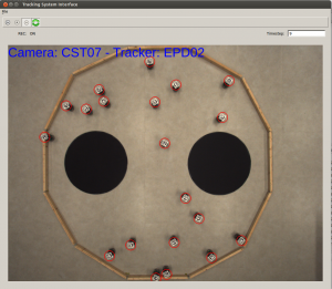
The Arena Viewer is an interactive GUI that helps the user setting up the experiment. With the Arena Viewer the user can see how the experiment is evolving in real time, and if a tracker has been defined in the experiment file the detected markers are highlighted. The Arena Viewer is helpful in the tuning phase before the real experiment, when the user must carefully balance the environmental light with camera acquisition parameters such as exposure time and gain. It is also helpful during the run of the experiment, because it allows the user to stop the recording/tracking of the experiment, make some changes in the arena and start again.
WARNING: All the options selected in the experiment file are reported unchanged in the Arena Viewer.
!!!WARNING!!! As a matter of performance, the refreshing operation of the frames in the Arena Viewer is very time consuming, degrading the performance of the Tracking System and the overall FPS. Therefore, the refresh toggle button (two green circular arrows) allows the user to enable or disable the refresh of the image. It is best practice to disable the refresh of the images after the tune of the experiment is done.
Adapter for the cameras
In case you need an adaptor for the cameras to attach them to a standard camera mount (e.g., Manfrotto), you can create one using the laser cutter. Here are the files: ecp version dxf version


