Supplementary material for the paper
The TAM: abstracting complex tasks
in swarm robotics research
Arne Brutschy, Lorenzo Garattoni, Manuele Brambilla, Gianpiero Francesca, Giovanni Pini, Marco Dorigo, and Mauro Birattari
Last change: November 11th, 2014
|
Submitted to the Journal of Swarm Intelligence Related IRIDIA Technical Report: TR/IRIDIA/2010-015 Table of Contents |
1. Introduction
This page provides multimedia and technical information for the TAM, a device used for task abstraction in experiments involving the e-puck robot.
For further technical information, please see the GitHub page of the TAM.
The paper has been submitted to the Journal of Swarm Intelligence.
1.1 Note on versions
Please note that this page gives the details for the prototype version of the TAM
as used for the experiments in the paper (version 5, revision D). The information
on this page will remain constant, even if there is a new version of the TAM.
For the latest version of the TAM including all CAD files, soft- and firmware, central
controlling framework etc., please see
the GitHub page of the TAM.
Current version: version 5, revision D
1.2 Abstract of the paper
Research in swarm robotics focuses mostly on how robots interact and cooperate to perform tasks, rather than on the details of task execution. As a consequence, researchers often consider abstract tasks in their experimental work. For example, foraging is often studied without physically handling objects: the retrieval of an object from a source to a destination is abstracted into a trip between the two locations—no object is physically transported. Despite being commonly used, so far task abstraction has only been implemented in an ad-hoc fashion.
In this paper, we propose a new approach to abstracting complex tasks in swarm robotics research. This approach is based on a physical device called the task abstraction module (\TAM) that abstracts single-robot tasks to be performed by an e-puck robot. A complex multi-robot task can be abstracted using a group of TAMs by first modeling the task as the set of its constituent single- robot subtasks and then abstracting each subtask with a TAM. We present a collection of tools for modeling complex tasks, and a framework for controlling a group of TAMs such that the behavior of the group implements the model of the task. The TAM enables research on cooperative behaviors and complex tasks with simple, cost-effective robots such as the e-puck—research that would be difficult and costly to conduct using specialized robots or ad-hoc task abstraction.
We demonstrate how to abstract a complex task with multiple TAMs in an example scenario involving a swarm of e-puck robots.
Keywords: Swarm robotics, task allocation, task partitioning, swarm intelligence, robotics, e-puck
1.3 Demo videos
2. The TAM
This section gives the technical details of the TAM.
2.1 License
The work presented in this section is licensed under a
 Creative Commons Attribution-NonCommercial-ShareAlike 3.0 Unported License.
2.2 Photos
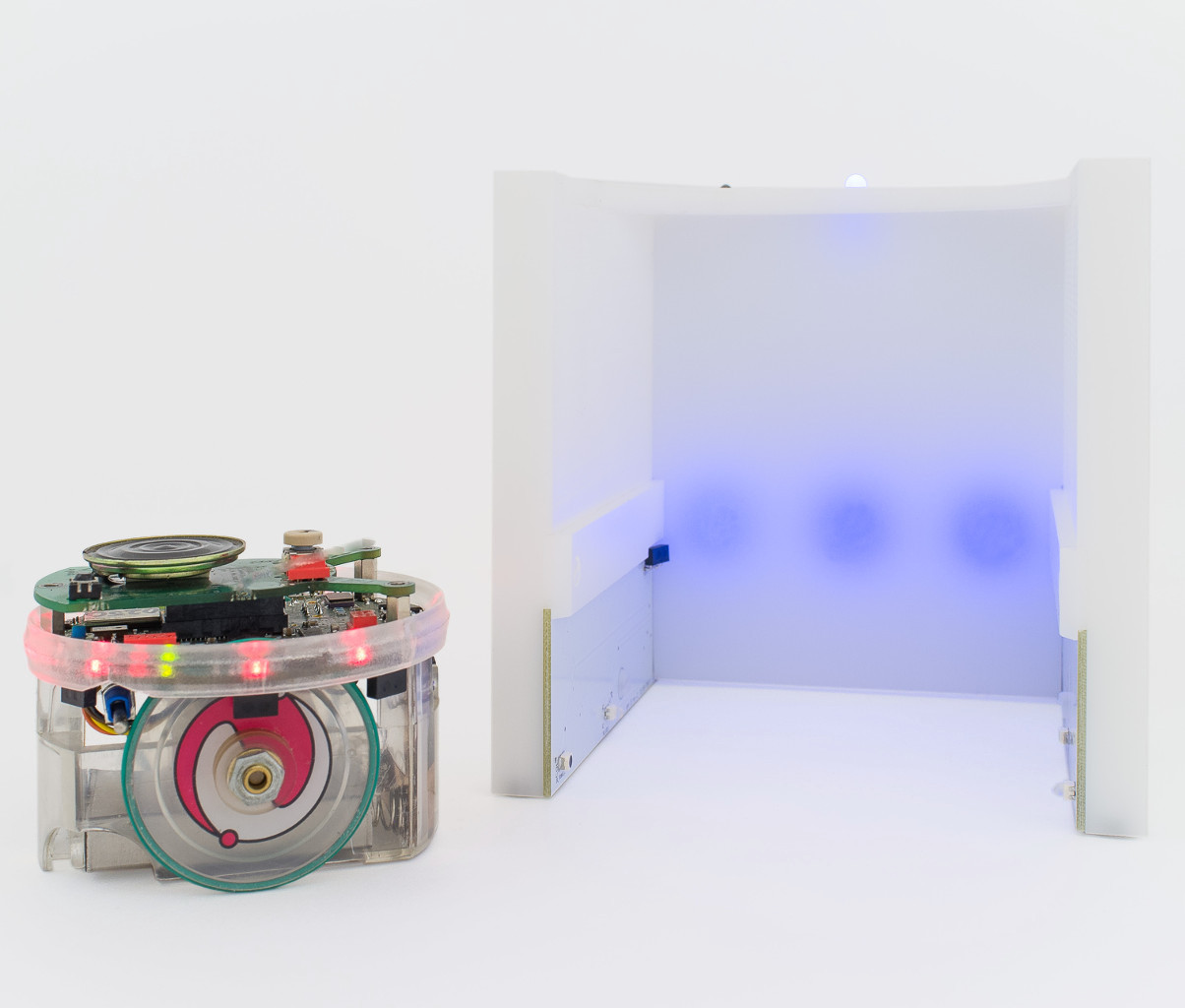 Figure 2.2a: The TAM with an e-puck that has no extensions.
The sensors relevant to the TAM are the forward facing camera for the detection of the TAM and the IR transceiver for communication with the TAM.
Figure 2.2a: The TAM with an e-puck that has no extensions.
The sensors relevant to the TAM are the forward facing camera for the detection of the TAM and the IR transceiver for communication with the TAM.
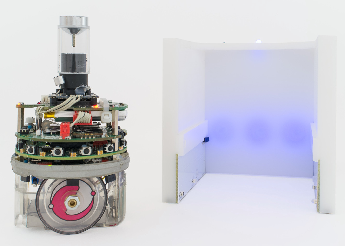 Figure 2.2b: The TAM with an e-puck that has several extensions: the range and bearing sensor, the embedded computer running Linux, and the omni-directional camera. The TAM is compatible with all these extensions; the omni-directional camera is used to detect the TAM instead of the forward facing camera, if present.
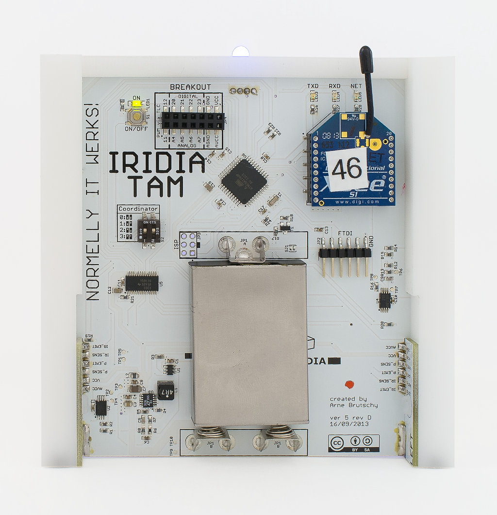 Figure 2.2c: The TAM seen from the back. The TAM features a 2.4 GHz IEEE 802.15.4 mesh networking module that allows it to exchange data with other TAMs and the researcher's workstation.
The battery is the same one used for the e-puck robot, which eases charging and handling of the batteries during the course of an experiment.
Figure 2.2c: The TAM seen from the back. The TAM features a 2.4 GHz IEEE 802.15.4 mesh networking module that allows it to exchange data with other TAMs and the researcher's workstation.
The battery is the same one used for the e-puck robot, which eases charging and handling of the batteries during the course of an experiment.
2.3 Electronics - schematics
The TAM consists of three boards: the mainboard in the middle, which holds the main electronics (micro-controller, radio transceiver, battery etc.). The left board and right board, on the two sides of the TAM (seen from the front). Below, you can see the schematics of the three boards.
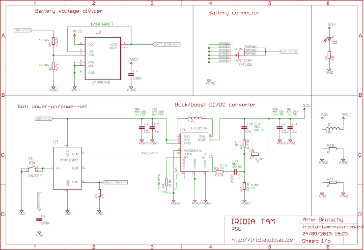
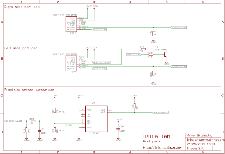
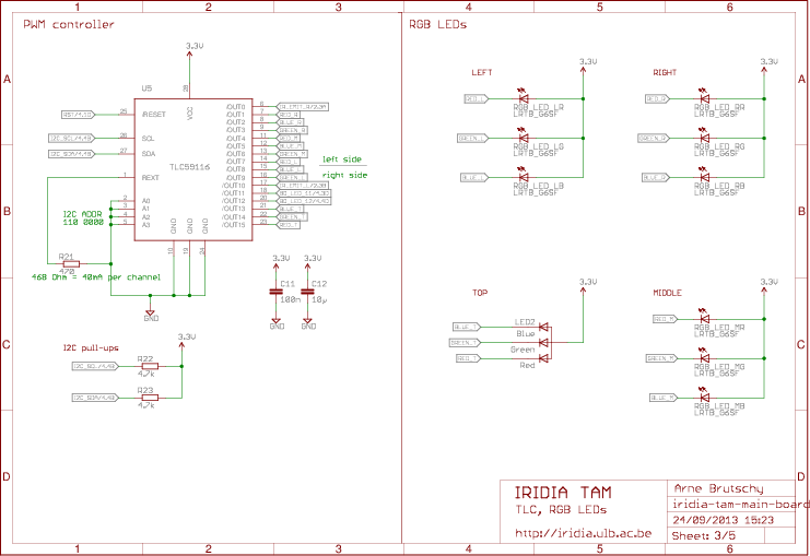
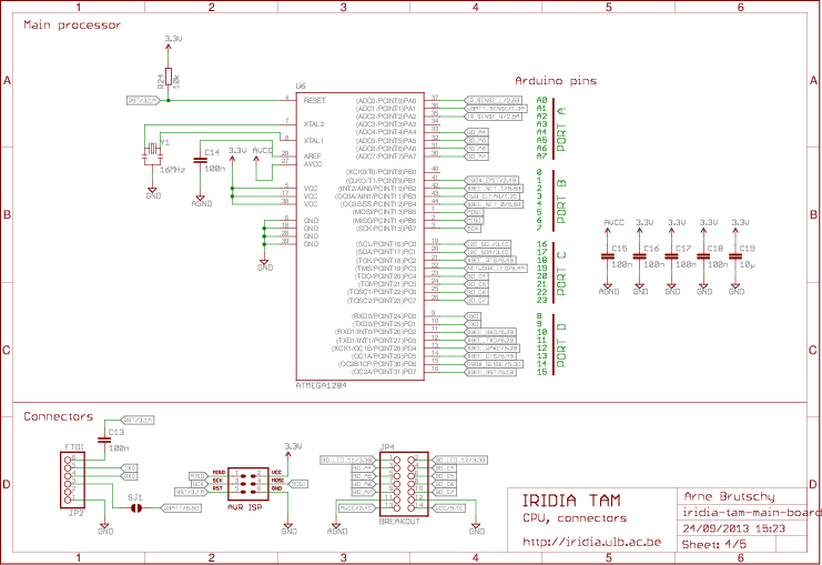
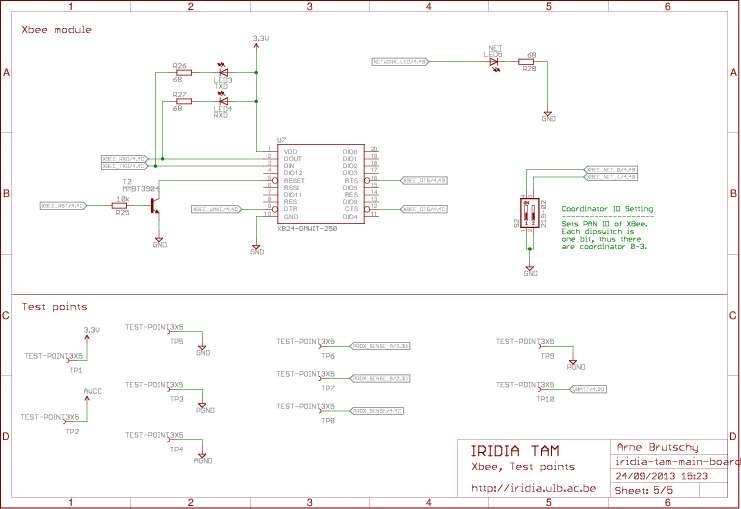 Figure 2.3a: The schematics of the main board, including the main electronics (micro-controller, radio transceiver, battery etc.).
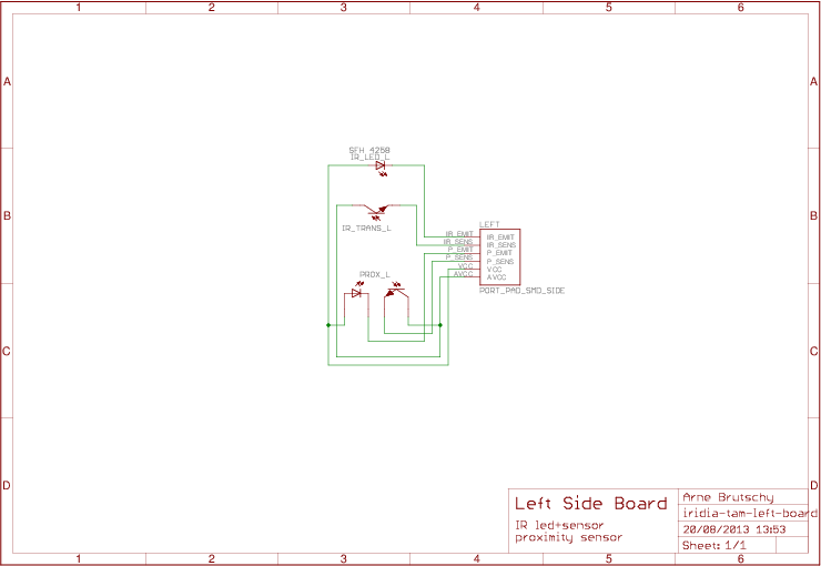 Figure 2.3b: The schematics of the left board, with one RGB LED, the proximity sensor and the IR LED for the light barrier.
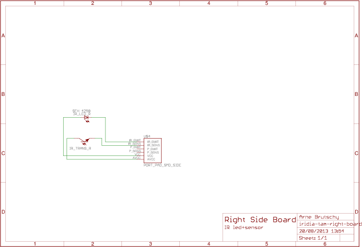 Figure 2.3c: The schematics of the right board, with one RGB LED and an IR transistor for the light barrier.
Download as PDF
2.4 Electronics - PCBs
Below, you can see the three PCBs.
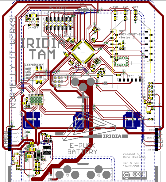 Figure 2.4a: The main board, including the main electronics (micro-controller, radio transceiver, battery etc.).
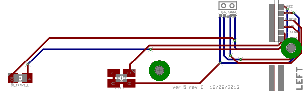 Figure 2.4b: The left board, with one RGB LED, the proximity sensor and the IR LED for the light barrier.
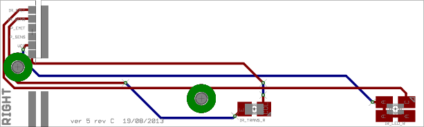 Figure 2.4c: The right board, with one RGB LED and an IR transistor for the light barrier.
Download as PDF
Download as Gerbers
2.5 Plastic body - plans
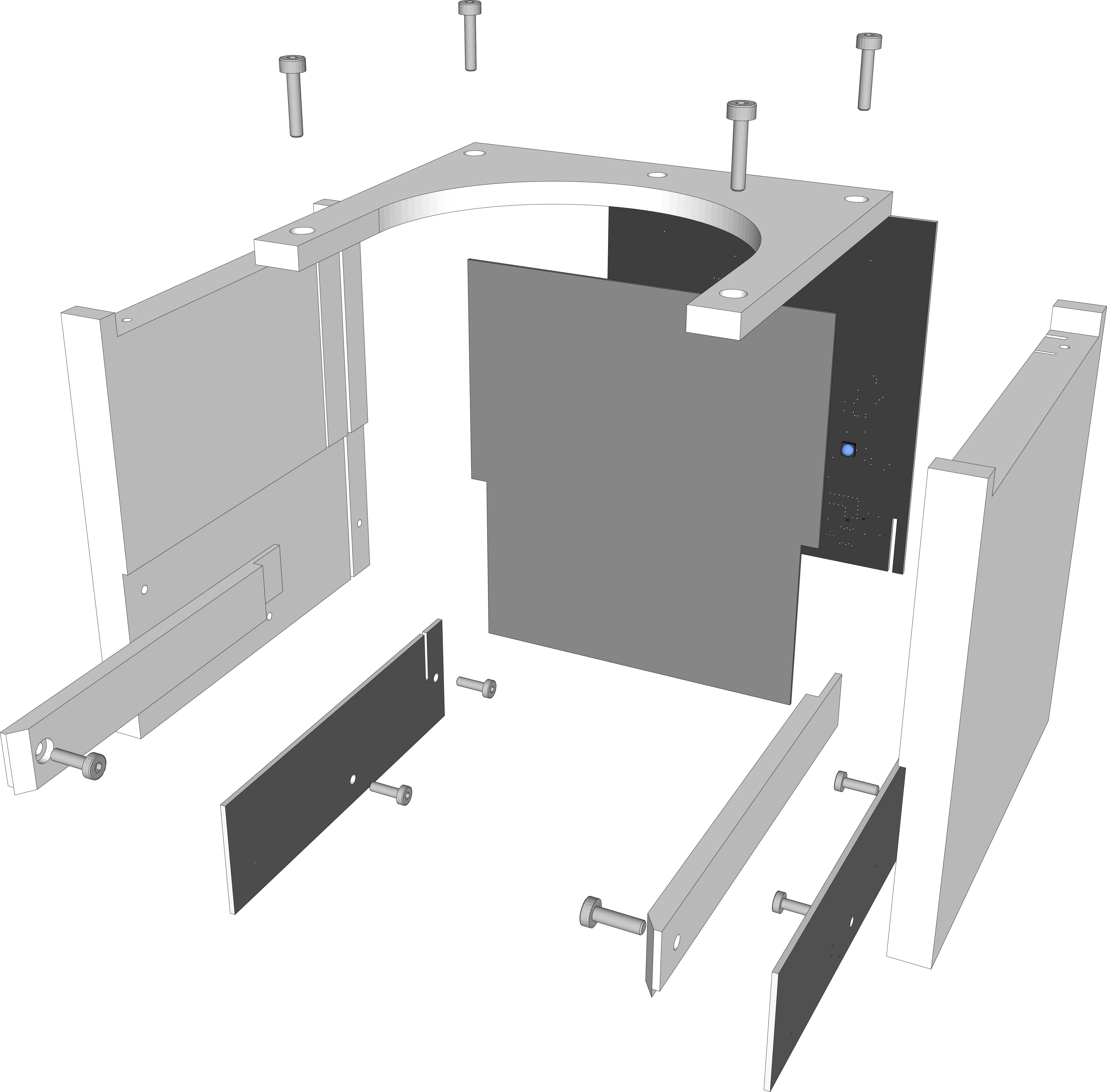 Figure 2.5: TAM, exploded view.
The TAM consists of four parts, machined from POM plastic: the two sides, the top bracket, and the diffuser. Below, we show only the isometric view on these four parts. Detailed plans can be downloaded compressed as a zip.
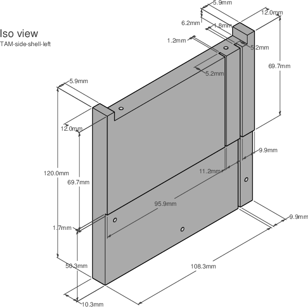 Figure 2.5a: TAM shell, left part.
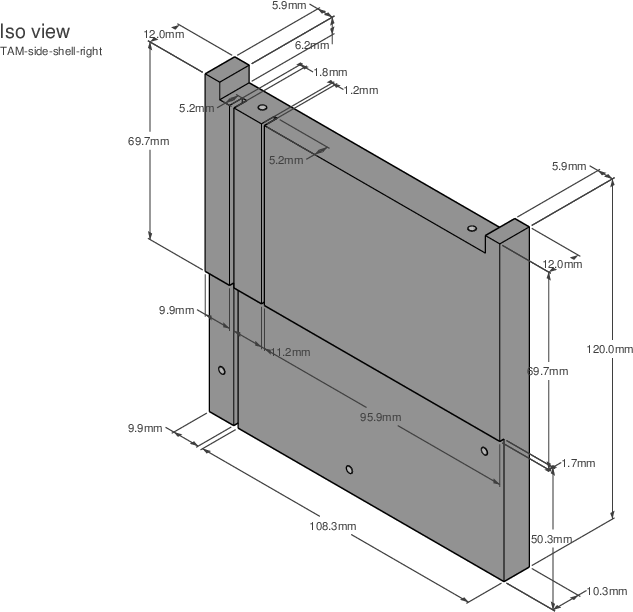 Figure 2.5b: TAM shell, right part.
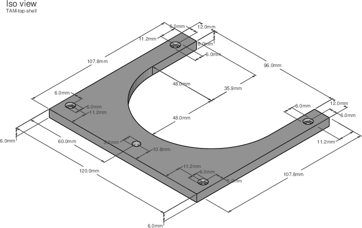 Figure 2.5c: TAM shell, top part.
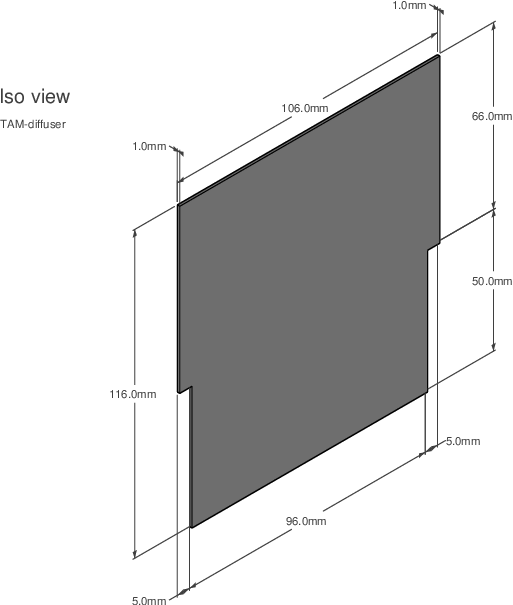 Figure 2.5d: TAM shell, diffuser.
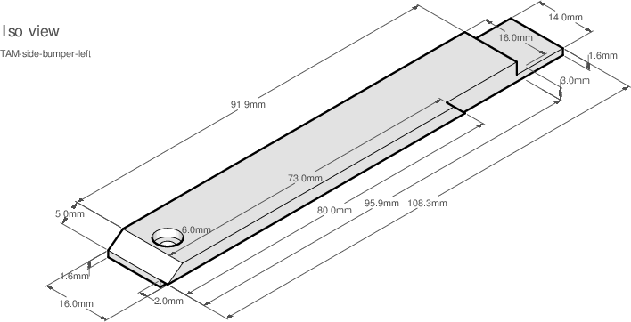 Figure 2.5d: TAM shell, bumper (left side).
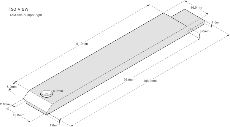 Figure 2.5d: TAM shell, bumper (right side).
Download as PDF
The ZIP contains all plans necessary to produce the TAM shell by a professional service.
2.6 Bill of materials
Download as PDF
Download as XLS
2.7 Extension and reproduction
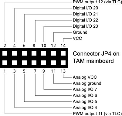 Figure 2.7: Extension connector of the TAM.
The philosophy of the TAM follows the extensibility of Arduino and of the e-puck. To this end, the TAM features an extension connector that allows researchers to extend its capabilities. Additionally to supplying power, the extension connector provides 10 input/output channels: 2 channels for PWM LED control, 4 digital channels and 4 analog channels. The variety of channels enables a wide range of possible extensions. An example of a possible extension is a light sensor that allows to model the day/night cycle of a colony by changing the behavior of a group of TAMs depending on the ambient light.
The license mentioned above allows others to modify and reuse the design as long as it remains open source. Additionally, the license grants the rights to produce the TAM commercially. All electronic components are common and easily sourceable from distributors all over the world. Apart from the electronic components, all parts can be produced in-house given hobbyist-level equipment. Nevertheless, we advise that the PCBs and the plastic parts of the body are produced by a professional service. The cost of the TAM is relatively low provided that final assembly is done in-house: the total cost of a single TAM is 140 EUR/TAM for a quantity of 50 TAMs (with the electronic components at ~60 EUR, the plastic parts for the body at ~60 EUR, and PCB including assembly at ~20 EUR).
Download as PDF
3. Reliability experiments
This section gives supplementary data for the TAM reliability experiments.
3.1 TAM visibility
 Figure 3.1: Visibility of the TAM when using an e-puck equipped with the omni-directional camera extension.
The e-puck has been placed with random orientations.
The asymmetric field of view results most likely from imperfections in the mirror of the omni-directional camera extension.
Figure 3.1: Visibility of the TAM when using an e-puck equipped with the omni-directional camera extension.
The e-puck has been placed with random orientations.
The asymmetric field of view results most likely from imperfections in the mirror of the omni-directional camera extension.
To obtain this image, an e-puck has been placed on a 10cm x 10cm grid that extends over a square meter. If the e-puck was able to perceive the TAM (located at the bottom of the image), it lit up its LEDs in red. Each placement has been recorded using an overhead camera, the resulting 100 images have been overlaid to produce this image. In the image, the ground has been edited in order to increase readability.
3.2 Experiment 1 (2 interrelated TAMs)
In this experiment, a single e-puck robot has to perform an complex task.
The complex task consists of two interrelated single-robot subtasks: the green task has to be executed before the blue task. The experiment is terminated once the battery of the robot is depleted. In the experiment shown in this video, the resulting runtime is 40 minutes, during which the robot executes a total of 48 complex tasks (hence, 96 single-robot tasks). No task failures occur during the runtime of the experiment.
Download data
- data of experiment 1 (log of the central controller)
3.3 Experiment 2 (50 non-interrelated TAMs)
In this experiment, two e-puck robots have to perform atomic tasks of two types: green and blue. At the beginning of the experiment, a total of 50 tasks are available (randomly chosen from the two task types). Tasks successfully performed do not become available anew. The experiment terminates after all tasks have been executed. In the experiment shown in this video, the resulting runtime is approximately 17 minutes.
Download data
- data of experiment 2 (log of the central controller)
4. Proof-of-concept demonstration
This section gives supplementary data for the proof-of-concept demonstration.
4.1 Full Petri net of the low-level model
 Figure 4.1: Full Petri net of the low-level model of the example task t_disaster.
The image is a screen capture of the low-level model reproduced in PIPE (Platform Independent Petri net Editor).
PIPE allows one to simulate a Petri net. The PIPE project file used to simulate the low-level model of the example task can be found below.
Note that the layout shown is the one produced by PIPE and cannot be freely modified due to limitations of PIPE.
Figure 4.1: Full Petri net of the low-level model of the example task t_disaster.
The image is a screen capture of the low-level model reproduced in PIPE (Platform Independent Petri net Editor).
PIPE allows one to simulate a Petri net. The PIPE project file used to simulate the low-level model of the example task can be found below.
Note that the layout shown is the one produced by PIPE and cannot be freely modified due to limitations of PIPE.
Download as PDF
4.2 Videos
Proof-of-concept demonstration 1
Proof-of-concept demonstration 1: single instance of a complex task consisting of 3 TAMs, 6 e-puck robots.
Proof-of-concept demonstration 2
Proof-of-concept demonstration 2: six instances of a complex task consisting of 3 TAMs (18 TAMs total), 20 e-puck robots.
4.3 Detailed data
This section contains detailed data for the proof-of-concept demonstrations.
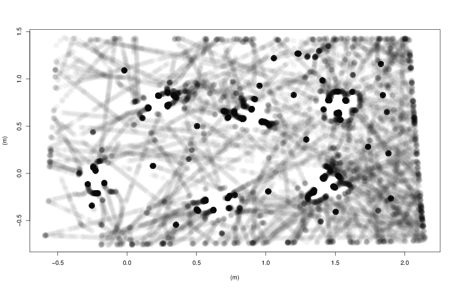 Figure 4.1: Tracking system data of demonstration 2. Dots present locations of robots over the course of the
demonstration. Darker regions represent higher robot density. The locations of the 6 task instances (TAMs) are
clearly visible.
Figure 4.1: Tracking system data of demonstration 2. Dots present locations of robots over the course of the
demonstration. Darker regions represent higher robot density. The locations of the 6 task instances (TAMs) are
clearly visible.
Download data
These ZIP files contain all logs and data taken during demonstration 1 and 2.
- data of demonstration 1 (logs of the central controller)
- data of demonstration 2 (logs of the central controller, tracking system data)