Libsboteye
Description
libsboteye2 is a program developped at IRIDIA that permits the sbots to have a rough visual sensing of their environment.
Where can I find it ?
It is currently located in the SVN repository of IRIDIA. Anybody that has a SSH access to the iridia server can retrieve the files. They are part of the CommonInterface project, that is not documented yet. If you retrieve the CommonInterface from svn (name : sbtoci), you'll get the last version of the libsboteye in the directory that contains code for real sbots. At the moment there is no information on how to login, and retrieve files.
How to compile/install ?
First retrieve the files, then using a command line go into the directory where the files were copied. The directory should be called 'sboteyelib2'.
As usually with swarmbots, you need to cross-compile. So first set your environment to use toolchain. As an example, you can use the following commands :
export TOOLCHAIN=$HOME/factory/sbots/toolchain/
export PATH=$PATH:$TOOLCHAIN/bin
export CPPFLAGS="-I $TOOLCHAIN/include"
export CCFLAGS="-I $TOOLCHAIN/include"
export LDFLAGS="-L$TOOLCHAIN/lib -static"

export BUILD_CC="/usr/bin/g++"
export CXX="arm-uclibc-g++"
export CC="arm-uclibc-gcc"
export LD="arm-uclibc-ld"
export AR="arm-uclibc-ar"
export RANLIB="arm-uclibc-ranlib"
Now, the library is composed of three main parts. A modified version of libjpeg, the library itself and findCenter. FindCenter is a tool to determine the location of the center of the robot in the pictures it takes. This is necessary to express relative positions of detected objects. The several parts can be built using the following commands (starting from the root directory of the project):
cd libjpeg
make clean
make
cd ../libsboteye
make clean
make
cd findCenter
make clean
make
cd ..
make
How does the program work ?
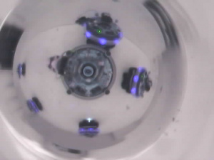
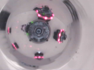
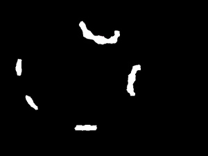
The library is identifying colours inside pictures retrieved from the USB camera of the robot. The program relies on a segmentation process to identify colours in the pictures. This is a very simple technic based on bounding boxes in the colour space. The segmentation is not done in RGB space which has poor properties for our purpose. Instead we have choosen the HSV space, a tradeoff between the quality of Lab space and the CPU required to go from RGB to Lab.
There are no explicit recognition of robots or any object. The program is just segmenting pictures and returning identified blocks of colours.
The maximum rate of the camera is currently set at 15 fps, but could be raised to 30. Taking into account the time required to analyze pictures and control sbots, controllers developped at IRIDIA are performing loops between 4 to 9 fps.
I shall give a quick introduction to the main aspects of the program now. Segment.c contains all the code required to achieve the segmentation process. The steps are roughly : take a picture, transform pixels from RGB to HSV. For each pixel, perform tests to determine the color. The test is made by the macro TESTCOLOR and is a basic bounding box checking. The parameters of the macro are very important. It is possible to use the same parameters for all the robots, but you will end up with some misperceptions. Depending on the postprocessing you apply on this detection and your controller, you might a more accurate detection. For this purpose, we have evaluated parameters for each robot individually.
The program is running several threads. One for achieving segmentation, on for retrieving the pictures from the camera. Results of the segmentation are put in buffers protected by mutex. To use the output of the program, you need to lock the buffer. There are two buffers : sharedObjects and sharedPictures. The structure of thoses buffers is available in sbotEye.h.
Many fields of those structures are not computed. The fields have been kept for compatibility issues. The interesting fields are x, y, dist_min and closest_pixel_dir in sharedObjects. Distance is a squared distance in centimeters, but the precision is arbitrary, so you should carry on some experiments to determine interesting values. The direction is an angle in radians * 10000.
The field raw of sharedPictures contains the uncompressed picture taken by the camera. The jpeg field contains the original jpeg...
Tools for extracting segmentation parameters
Some tools were built to find the right segmentation parameters. The tools are rudimentary but functional... Those tools are not in the CVS, but you can download them here : sboteyelib2Tools
Basic principle
Among the tools you can find intersect.cpp and plotKernels.cpp. Those two programs require parameters files as argument to run. I describe first their use, and second the syntax of the parameter files.
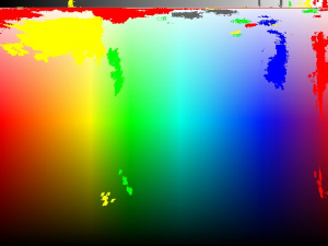
The goal is to draw on a spectrum file what the robot is perceiving. This way we can get insights on which colours are perceived, and which sources of light lie very close in the colour space and lead easily to misperceptions.
To make those spectrums, you need to take snapshots from the robots in experimental conditions. Take several pictures (at least 25) of identical situations. When I say identical, it means you shouldn't touch the robots, the preys or whatever. Just take 25 shots of the same situations, this is to take sensor noise into account. Snapshots have to be taken separately for different colours and, if accuracy is required, for different robots. In addition, you should put the same source of light at different distances. To speed up the process, it is possible to put at once multiple sources at different distance in one serie of shots.
Now you end up with 25 pictures for different robots and different colours. Each batch of pictures is supposed to be identical, so you can draw a mask. I use gimp to draw this mask : it has the same size as the pictures. The mask should be black with some white regions defining the places where the target colour is perceived by the robot.
Basically the program intersect will load your snapshots and discard pixels located in the black regions of the mask. All the pixels of the white regions are considered of interest. The program thus defines for each colour a set of pixels perceived by the robot. Then it compares the pixels between each sets. Pixels that are too close (distance L1, defined in RGB space by a threshold fixed in the program) are discarded. The remaining pixels are saved in files kernel*.txt (one file per category).
Now you can use the program plotKernels to draw the pixels on a colour spectrum. Once you have generated the spectrum, you know what the robot is perceiving.
You can use the program viewer which contains exactly the same detection code as the libsboteye2 to simulate the segmentation process carried out by the robots on pictures. Use this program with a spectrum and you will get the detection range of each colour.
The last thing to do is to match the spectrum describing the perception of the robots and the one describing the output of the segmentation process. This calibration requires to tune parameters by hand. Parameters that have already been extracted are provided below.
Syntax of configuration files
Intersect parameters file syntax
// size of the pictures
640 480

// the mask
mask.jpg

// Tolerance threshold (distance l1 in RGB space)
2.0

// colours count
2

// maximum number of pixels
1000000

// maximum number of files
100

// for the first colour :
// minimal and maximal values of the intensity of a pixel.
// the pixels with an intensity outside this range are ignored
// intensity = R + G + B
400.0 750.0

// the number of pictures used for this colour
50

// path to the snapshots
datas/gre-00.jpg datas/gre-01.jpg datas/gre-02.jpg datas/gre-03.jpg datas/gre-04.jpg datas/gre-05.jpg
datas/gre-06.jpg datas/gre-07.jpg datas/gre-08.jpg datas/gre-09.jpg datas/gre-10.jpg datas/gre-11.jpg
datas/gre-12.jpg datas/gre-13.jpg datas/gre-14.jpg datas/gre-15.jpg datas/gre-16.jpg datas/gre-17.jpg
datas/gre-18.jpg datas/gre-19.jpg datas/gre-20.jpg datas/gre-21.jpg datas/gre-22.jpg datas/gre-23.jpg
datas/gre-24.jpg datas/gre-25.jpg datas/gre-26.jpg datas/gre-27.jpg datas/gre-28.jpg datas/gre-29.jpg
datas/gre-30.jpg datas/gre-31.jpg datas/gre-32.jpg datas/gre-33.jpg datas/gre-34.jpg datas/gre-35.jpg
datas/gre-36.jpg datas/gre-37.jpg datas/gre-38.jpg datas/gre-39.jpg datas/gre-40.jpg datas/gre-41.jpg
datas/gre-42.jpg datas/gre-43.jpg datas/gre-44.jpg datas/gre-45.jpg datas/gre-46.jpg datas/gre-47.jpg
datas/gre-48.jpg datas/gre-49.jpg

// Now repeat the process for the second colour
// intensity min and max
400.0 750.0

// nb of files
50

// path to snapshots
datas/blu-00.jpg datas/blu-01.jpg datas/blu-02.jpg datas/blu-03.jpg datas/blu-04.jpg datas/blu-05.jpg
datas/blu-06.jpg datas/blu-07.jpg datas/blu-08.jpg datas/blu-09.jpg datas/blu-10.jpg datas/blu-11.jpg
datas/blu-12.jpg datas/blu-13.jpg datas/blu-14.jpg datas/blu-15.jpg datas/blu-16.jpg datas/blu-17.jpg
datas/blu-18.jpg datas/blu-19.jpg datas/blu-20.jpg datas/blu-21.jpg datas/blu-22.jpg datas/blu-23.jpg
datas/blu-24.jpg datas/blu-25.jpg datas/blu-26.jpg datas/blu-27.jpg datas/blu-28.jpg datas/blu-29.jpg
datas/blu-30.jpg datas/blu-31.jpg datas/blu-32.jpg datas/blu-33.jpg datas/blu-34.jpg datas/blu-35.jpg
datas/blu-36.jpg datas/blu-37.jpg datas/blu-38.jpg datas/blu-39.jpg datas/blu-40.jpg datas/blu-41.jpg
datas/blu-42.jpg datas/blu-43.jpg datas/blu-44.jpg datas/blu-45.jpg datas/blu-46.jpg datas/blu-47.jpg
datas/blu-48.jpg datas/blu-49.jpg
PlotKernels parameters file syntax
// dimensions of the picture
640 480

// a path to the spectrum file
spectrum.jpg

// tolerance threshold for drawing
4

// number of kernel files or colours categories available
5

// RGB components to plot on the spectrum followed by the path to set of pixels to plot
255 0 0 kernel0.txt
0 255 0 kernel1.txt
0 0 255 kernel2.txt
255 255 0 kernel3.txt
100 100 100 kernel4.txt
Viewer syntax
The parameters of the colours are located line 341 in the source code.
./viewer parameter_file picture1 [picture2 picture3...]
Some parameters already extracted
- EPFL, generic
TESTCOLOR(r, g, b, intensity, RED,    925, 1000, 1000, 75, 750, 600);
TESTCOLOR(r, g, b, intensity, GREEN,  285, 1000, 1000, 65, 670, 400);
TESTCOLOR(r, g, b, intensity, BLUE,   635, 1000, 1000, 68, 700, 500);
TESTCOLOR(r, g, b, intensity, YELLOW, 105, 520,  1000, 55, 300, 700);
- IRIDIA, generic
TESTCOLOR(r, g, b, intensity, RED,    925, 1000, 1000, 75, 550, 600);
TESTCOLOR(r, g, b, intensity, GREEN,  310, 1000, 1000, 65, 670, 600);
TESTCOLOR(r, g, b, intensity, BLUE,   670, 1000, 1000, 50, 680, 500); // 700 600
TESTCOLOR(r, g, b, intensity, YELLOW, 130, 600,  1000, 70, 300, 700);
- EPFL, robot 32
TESTCOLOR(r, g, b, intensity, RED,    925, 1000, 1000, 75, 590, 700);
TESTCOLOR(r, g, b, intensity, GREEN,  275, 1000, 1000, 48, 620, 630);
TESTCOLOR(r, g, b, intensity, BLUE,   650, 1000, 1000, 68, 700, 500);
TESTCOLOR(r, g, b, intensity, YELLOW, 110, 500,  1000, 75, 220, 700);
- EPFL, robot 08
// -> I need the bigger spectrums to be more precise. Difficult to have a good green without destroying yellow.
TESTCOLOR(r, g, b, intensity, RED,    925, 1000, 1000, 75, 630, 600);
TESTCOLOR(r, g, b, intensity, GREEN,  190, 1000, 1000, 65, 670, 650);
TESTCOLOR(r, g, b, intensity, BLUE,   680, 1000, 1000, 50, 600, 500);
TESTCOLOR(r, g, b, intensity, YELLOW, 80,  520,  1000, 50, 220, 700);
- EPFL, robot 35
TESTCOLOR(r, g, b, intensity, RED,    925, 1000, 1000, 75, 590, 700);
TESTCOLOR(r, g, b, intensity, GREEN,  275, 1000, 1000, 48, 620, 630);
TESTCOLOR(r, g, b, intensity, BLUE,   650, 1000, 1000, 68, 700, 500);
TESTCOLOR(r, g, b, intensity, YELLOW, 110, 500,  1000, 75, 220, 700);
- EPFL, robot 11
TESTCOLOR(r, g, b, intensity, RED,    925, 1000, 1000, 75, 670, 600);
TESTCOLOR(r, g, b, intensity, GREEN,  265, 1000, 1000, 45, 520, 580);
TESTCOLOR(r, g, b, intensity, BLUE,   650, 1000, 1000, 68, 700, 500);
TESTCOLOR(r, g, b, intensity, YELLOW, 110, 520,  1000, 55, 220, 700);
- EPFL, robot 10
TESTCOLOR(r, g, b, intensity, RED,    925, 1000, 1000, 75, 670, 600);
TESTCOLOR(r, g, b, intensity, GREEN,  285, 1000, 1000, 65, 670, 580);
TESTCOLOR(r, g, b, intensity, BLUE,   650, 1000, 1000, 68, 700, 500);
TESTCOLOR(r, g, b, intensity, YELLOW, 120, 500,  1000, 63, 220, 700);
- EPFL, robot 06
TESTCOLOR(r, g, b, intensity, RED,    925, 1000, 1000, 75, 670, 600);
TESTCOLOR(r, g, b, intensity, GREEN,  280, 1000, 1000, 70, 760, 580);
TESTCOLOR(r, g, b, intensity, BLUE,   650, 1000, 1000, 68, 700, 500);
TESTCOLOR(r, g, b, intensity, YELLOW, 117, 423,  1000, 60, 220, 700);
- EPFL, robot 02
TESTCOLOR(r, g, b, intensity, RED,    925, 1000, 1000, 75, 750, 600);
TESTCOLOR(r, g, b, intensity, GREEN,  285, 1000, 1000, 65, 670, 400);
TESTCOLOR(r, g, b, intensity, BLUE,   635, 1000, 1000, 68, 700, 500);
TESTCOLOR(r, g, b, intensity, YELLOW, 110, 423,  1000, 42, 220, 700);
- EPFL, robot 33
TESTCOLOR(r, g, b, intensity, RED,    925, 1000, 1000, 75, 600, 650);
TESTCOLOR(r, g, b, intensity, GREEN,  280, 1000, 1000, 35, 550, 200); // part up
TESTCOLOR(r, g, b, intensity, GREEN,  303, 1000, 1000, 35, 100, 700); // part middle down
TESTCOLOR(r, g, b, intensity, GREEN,  275, 1000, 1000, 40, 100, 200); // up down
TESTCOLOR(r, g, b, intensity, GREEN,  300, 1000, 260,  45, 120, 125); // down down...
TESTCOLOR(r, g, b, intensity, BLUE,   670, 1000, 1000, 50, 650, 780);
TESTCOLOR(r, g, b, intensity, YELLOW, 115, 400,  1000, 60, 140, 500);
- EPFL, robot 17
// -> so far, I manage to avoid too much misperceptions, but the ranges are bad.
TESTCOLOR(r, g, b, intensity, RED,    925, 1000, 1000, 75, 530, 700);
TESTCOLOR(r, g, b, intensity, GREEN,  275, 720,  1000, 35, 250, 500); // part up
TESTCOLOR(r, g, b, intensity, GREEN,  303, 1000, 1000, 35, 100, 500); // part middle down
TESTCOLOR(r, g, b, intensity, BLUE,   680, 1000, 1000, 40, 730, 400);
TESTCOLOR(r, g, b, intensity, YELLOW, 105, 400,  1000, 80, 140, 500);
- EPFL, robot 13
TESTCOLOR(r, g, b, intensity, RED,    925, 1000, 1000, 75, 700, 600);
TESTCOLOR(r, g, b, intensity, GREEN,  275, 430, 1000,  35, 100, 500); // part up
TESTCOLOR(r, g, b, intensity, GREEN,  303, 1000, 1000, 35, 100, 500); // part middle down
TESTCOLOR(r, g, b, intensity, GREEN,  290, 1000, 1000, 35, 100, 200); // up down
TESTCOLOR(r, g, b, intensity, GREEN,  300, 1000, 260,  45, 100, 125); // down down...
TESTCOLOR(r, g, b, intensity, BLUE,   660, 1000, 1000, 60, 710, 700);
TESTCOLOR(r, g, b, intensity, YELLOW, 95, 400,  1000,  65, 140, 500);
- IRIDIA, robot 31
TESTCOLOR(r, g, b, intensity, RED,    925, 1000, 1000, 75, 670, 600);
TESTCOLOR(r, g, b, intensity, GREEN,  280, 1000, 1000, 85, 800, 620);
TESTCOLOR(r, g, b, intensity, BLUE,   670, 1000, 1000, 65, 700, 750);
TESTCOLOR(r, g, b, intensity, YELLOW, 105, 423,  1000, 75, 160, 700);
- IRIDIA, robot 26
TESTCOLOR(r, g, b, intensity, RED,    925, 1000, 1000, 75, 620, 600);
TESTCOLOR(r, g, b, intensity, GREEN,  280, 1000, 1000, 80, 880, 480);
TESTCOLOR(r, g, b, intensity, BLUE,   670, 1000, 1000, 65, 700, 750);
TESTCOLOR(r, g, b, intensity, YELLOW, 105, 423,  1000, 70, 130, 700);
- IRIDIA, robot 15
TESTCOLOR(r, g, b, intensity, RED,    925, 1000, 1000, 75, 670, 600);
TESTCOLOR(r, g, b, intensity, GREEN,  280, 1000, 1000, 65, 900, 500); // part up
TESTCOLOR(r, g, b, intensity, BLUE,   650, 1000, 1000, 68, 700, 500);
TESTCOLOR(r, g, b, intensity, YELLOW, 95, 423,  1000, 80, 220, 700);
- IRIDIA, robot 30
TESTCOLOR(r, g, b, intensity, RED,    925, 1000, 1000, 75, 620, 600);
TESTCOLOR(r, g, b, intensity, GREEN,  265, 1000, 1000, 80, 730, 580);
TESTCOLOR(r, g, b, intensity, BLUE,   650, 1000, 1000, 75, 620, 500);
TESTCOLOR(r, g, b, intensity, YELLOW, 85, 480,  1000, 65, 175, 700);
- IRIDIA, robot 18
TESTCOLOR(r, g, b, intensity, RED,    925, 1000, 1000, 75, 575, 700);
TESTCOLOR(r, g, b, intensity, GREEN,  275, 1000, 1000, 75, 690, 300); // part up
TESTCOLOR(r, g, b, intensity, GREEN,  325, 1000, 560,  55, 120, 200); // down down...
TESTCOLOR(r, g, b, intensity, BLUE,   650, 1000, 1000, 68, 750, 500);
TESTCOLOR(r, g, b, intensity, YELLOW, 110, 450,  1000, 65, 160, 700);
FAQ
My sbot is crashing a lot, can you help ?
Well this is totally off topic, but I just feared that some people wouldn't have the info. So I drop it here... problems with the usb have been identified on the sbot. This has an impact on the camera driver because one of his USB request will never be handled. Then the module just destroys the kernel and the robot crashes. This problem occurs when using the WIFI (which is also USB). First of all, it is possible to know when a robot is about to crash because of the camera, just take a look at the logs, using dmesg. If you see any of the following :
eth0: Information frame lost.
usb.c: selecting invalid interface 0
ov51x.c: Set packet size: set interface error
reboot safely the robot and avoid a dirty crash.
Now there is a way to avoid this problem : never transfer files of more than 100kBytes through wifi. If you have to transfer big files, just split them (using split) for the transfer and merge the parts on the robots using cat. Please see also below for a script to automatize safe transfers.
What are the usual colour settings of the sbots ?
All our parameters were extracted with the following colours settings :
- red : 15 0 0
- green : 0 15 0
- blue : 0 0 15
- yellow : 5 15 0
Is it possible to detect blinking leds ?
There is no such things in the library. Now nothing prevents you from writing code on the top of the library to do so. You need to take care of the framerate of the sbots. For example if you have only 4 frames per second, you can detect blinking at 2Hz maximum.
Is there a shift in the orientation of the robot ?
The complete question was : on the pictures, the gripper of the sbot is not perfectly horizontally aligned. Does this have consequences on the computation of the angle of objects ?
Answer is yes, there are consequences. When an object is perceived at an angle of 0 radians, there is a small shift with the direction of the gripper. The solution is to add a shift to the computed angle.
People in IRIDIA use the following piece of code :
#define CAMERA_OFFSET 163

  for(i = 0; i < numObjects; i++)
  {
    directions[i] = (objects[i].closest_pixel_dir) * 180 / 31400 + CAMERA_OFFSET;
    if (directions[i] < 0) directions[i] += 360;
    else if (directions[i] > 360) directions[i] -= 360;
  }
What is the reliability of colour detection
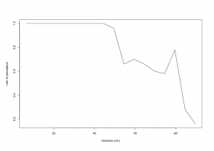
Or : should I average measures over 1 or 2 seconds to improve the results. Answer : if the range of necessary perception is low (for red, below 50 cm) then you can safely use single measures. As soon as you push the limits of the detection you should use some tricks to enhance perception, and I think especially about averaging several measures. Here is a picture of the reliability of detection (how much times a red led was detected in 50 trials)
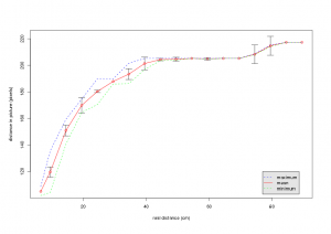
What is the relationship between distance perceived and actual distance ?
Well, there is a relationship that looks like a log (I didn't make a fit). For small distances (below 40 cm) you can assume a linear relationship. Over this distance, you need to rely on the data presented in the picture. The shape of this curve is caused by the spherical mirror of the sbot. The step at the end of the plot is simply due to the libsboteye that uses blocks of pixels to detect objects. That method is fast but has a very bad distance precision for objects located far away.
More tools
A script to get automatically the samples
Kevin Frugier, a student working in EPFL, has wrote this small script.
#!/bin/sh
if [ $# -ne 1 ]
then
echo "usage ./getData.sh [robot_name]"
exit 1
fi

echo "Getting pics from robot " $1
nb_pic=25

for color in red green blue
  do
  echo "Set lights to "$color" and press Enter"
  read
  for i in $(seq -w $nb_pic)
    do
    ssh root@$1 ./getjpeg
    scp root@$1:image-00.jpg ./$color$i.jpg
    echo $color$i".jpg"
  done
done
Safely send files to sbots
Another script provided by Kevin Frugier, from EPFL. This section is duplicated here
Usage : ./give.sh sbot10 pic*.bmp
Remark : binaries are stripped using a specific tool, take care of the line yourself :-)
#!/bin/sh
if [ $# -lt 2 ]
then
echo "usage : $0 [robot_name] [file1] [file2] [file...]"
exit 1
fi

robot=$1

for id_file in $(seq 2 $#)
  do
  shift
  echo "[$1]"
  echo "Striping (it can fail if it is not an arm binary)"
  /usr/arm/arm-linux/bin/strip $1
  echo "Spliting"
  split $1 $1.part -a 3 -b 100k -d &&
  echo "Transfering .part files"
  scp $1.part* root@$robot:. &&
  echo "Removing local .part files"
  rm $1.part*
  echo "Concatening distant .part files"
  ssh root@$robot "cat $1.part* > $1" &&
  echo "Removing distant .part files"
  ssh root@$robot "rm $1.part*"
done
More questions ?
Feel free to send comments, questions or insults to us : [1]. The main person in charge of the library at the moment is Alexandre Campo Feel free to improve the program and send patches. They will be inserted in the program.

